Tutorials#
This page contains tutorials on how to use Anri.
Crystallography#

Geometry#
Goniometer#
Anri currently uses the FABLE geometry definitions for converting to and from detector, laboratory and sample coordinate systems.
Please see the included FABLE geometry document for their definitions.
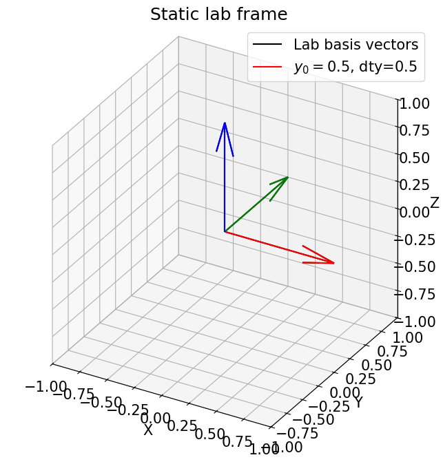
As that document isn’t perfectly descriptive, I’ll try to describe slightly more what convention we use. We use a right-handed coordinate system. With no goniometer rotations (all angles zero), the \(\omega\) rotation axis (vertical) defines our \(Z\) direction. The dty stage defines the \(Y\) axis, and the \(X\) axis (approximately down-beam) is perpendicular to \(Y\) and \(Z\). If you are the beam, looking towards the detector from the source, the \(Y\) axis points to the left.
Our goniometer stack is as follows:
omega - roll around Z axis
chi - roll around X axis
wedge - roll around Y axis (in ImageD11 this has a negative sign, we definine it as positive.)
dty stage - horizontal translation. Defines Y axis.
Hutch floor
General rotation functions like anri.geom.rot_z() work thusly.
Imagine the most basic stage, with a single rotation about \(Z\).
We want to generate a rotation matrix that encodes the pose of the stage.
When we receive the matrix \(\matr{R_z}\), it is applied like this:
Detector#
Something about detector space.
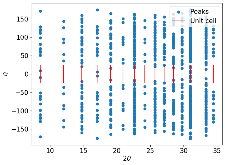
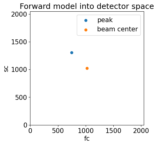
Forward Modeling#
There’s a very basic demonstration of how to perform a forward model with Anri.